This is a response to a question posted on the irrlicht forums at
here
PDF file:
Closest point on an ellipsoid to a point in space (to come)
If one wants to know the closest point on an ellipsoid to another point in
space, it can be found using constrained nonlinear optimization. It was stated
in the forum thread that there is no closed-form solution to this problem,
though I find that rather surprising. I will update this post if I can confirm
(or confirm an opposition) to that fact.
In any case, given a point $latex \vec{p}$ in space, where
$$ \vec{p} = \begin{bmatrix} p_x && p_y && p_z \end{bmatrix} $$
we want to find a point $latex \vec{q}$ that minimizes the euclidean distance
to $latex \vec{p}$ subject to the contraint that it is on an ellipsoid with the
following functional description
$$ \frac{x^2}{a^2} + \frac{y^2}{b^2} + \frac{z^2}{c^2} = 1 $$
This corresponds to the minimization of the following cost function (the
"cost" is the distance to the target point)
$$ J(\vec{q}) = \sqrt{ (p_x-q_x)^2 + (p_y-q_y)^2 + (p_z-q_z)^2 } $$
subject to the following constraint (which just says that it must be on the
ellipsoid)
$$ f(\vec{q}) = \frac{q_x^2}{a} + \frac{q_y^2}{b} + \frac{q_z^2}{c} - 1 =
0 $$
Now there are many ways to solve this problem. I will outline two of them here
known as steepest descent (or gradient search) and the leGrange method.
Steepest Descent
First comes steepest decent, because it is the easiest to understand
graphically. The goal here is that, starting at some point on the ellipse, we
will look at how the value of the cost function changes depending on the
direction we move, and choose to move in the direction that most improves the
cost. To begin with, let us redefine the problem in terms of two independent
variables, and let the third be dependent. In the following formulation, I
will choose $latex q_z$ to be the dependent variable, but you should note that
this is not always the best choice. A good choice of dependent variable is to
look at the coordinates of the target point and pick the one that is furthest
from the origin (to avoid numerically ill-conditioned situations).
Using $latex q_z$ as the dependent variable we can reformulate the constraint
as the following
$$q_z = \pm c \sqrt{ 1 - \frac{q_x^2}{a^2} - \frac{q_y^2}{b^2} }$$
Given this, we exam the effect that changing each of our independent variables
has on our cost function, by calculating the partial derivatives. First
though, we note that the minimum of a square root expression will occur at the
same point as the minimum of the argument, so we will throw away the square
root part and use
$$ J = (p_x-q_x)^2 + (p_y-q_y)^2 + (p_z-q_z)^2 $$
for the derivatives instead.
$$ \frac{ \partial J }{ \partial q_x } = -2(p_x - q_x) + -2(p_z -
q_z)\frac{ \partial q_z }{ \partial q_x }$$
$$ \frac{ \partial J }{ \partial q_y } = -2(p_y - q_y) + -2(p_z -
q_z)\frac{ \partial q_z }{ \partial q_y }$$
And given the equation above for $latex q_z$ we can determine the following
$$ \frac{ \partial q_z }{ \partial q_x } = \pm c \frac{1}{2} \sqrt{ 1 -
\frac{q_x^2}{a^2} - \frac{q_y^2}{b^2} }^{-\frac{1}{2}} \left( -2
\frac{q_x}{a^2}\right)$$
which simplifies to
$$ \frac{ \partial q_z }{ \partial q_x } = \mp \frac{c}{a^2}
\frac{q_x}{q_z}$$
and similarly
$$ \frac{ \partial q_z }{ \partial q_y } = \mp \frac{c}{b^2}
\frac{q_y}{q_z}$$
Note that the sign of these derivatives is opposite the sign of $latex q_z$.
Therefore we see the following
$$ \frac{ \partial J }{ \partial q_x } = -2(p_x - q_x) + 2 sign(q_z) (p_z
- q_z) \left( \frac{c}{a^2} \frac{q_x}{q_z} \right)$$
$$ \frac{ \partial J }{ \partial q_y } = -2(p_y - q_y) + 2 sign(q_z) (p_z
- q_z) \left( \frac{c}{b^2} \frac{q_y}{q_z} \right)$$
where $latex sign(x)$ is the signum function and returns $latex -1$ if the
argument is less than zero ($latex x < 0$) or $latex 1$ if the argument is
greater than zero ($latex x > 0$).
Now we solve for the minimum point using the following algorithm
- start at some $latex q_x$ and $latex q_y$
- calculate $latex \pm q_z$
- pick whichever of the two is closer by picking the one with the same sign as $latex p_z$
- calculate the cost $latex J$
- if $latex J$ of the current iteration is within some tolerance of $latex J$ at the previous iteration, stop here
- calcluate $latex \frac{\partial J}{\partial q_x}$ and $latex \frac{\partial J}{\partial q_y}$
- calculate $latex \Delta x$ and $latex \Delta y$ from $latex J$, $latex \frac{\partial J}{\partial q_x}$, and $latex \frac{\partial J}{\partial q_y}$
- update $latex q_x$ and $latex q_y$ using $latex \Delta x$ and $latex \Delta y$
- return to (1)
Here is a matlab code that demonstrates this algorithm. Note that in this
code, for the initial guess I use the intersection of the line segment between
the origin of the ellipse and $latex \vec{p}$ with the surface of the ellipse.
    clc;
    clear;

    % define the ellipsoid parameters
    a   = 3;
    b   = 7;
    c   = 9;

    % createa a 100 x 100 point mesh for displaying the ellipsoid
    x   = linspace( -a, a, 50 );
    y   = linspace( -b, b, 50 );

    % calculate the z coordinates
    [X,Y]   = meshgrid(x,y);
    Zp      = c*sqrt(1 - X.*X/(a*a) - Y.*Y/(b*b) );
    Zm      = -Zp;

    % create the point we're going to calculate the closest too
    px = 3;
    py = 4;
    pz = 8;


    % create an initial guess by finding the intersection of the ray from the
    % centroid to point with the ellipsoid surface
    k = sqrt( 1 / ( (px^2)/(a^2) + (py^2)/(b^2) + (pz^2)/(c^2) ) );

    qx = k*px;
    qy = k*py;
    qz = k*pz;

    % this is the scale factor for our movement along the ellipse, this can
    % start off quite large because it will be reduced as needed
    s = 1;


    % this is the main loop, you'll want to put some kind of tolerance based
    % terminal condition, i.e. when the cost function (distance) is only
    % bouncing back and forth between a tolerance or something more tailored to
    % your application, I will stop when the distance is +/- 1%
    i = 1;
    while 1
        % calculate the z for our given x and y
        qz_plus     = c * sqrt( 1 - qx*qx/(a*a) - qy*qy/(b*b) );
        qz_minus    = - qz_plus;

        % we want the one that get's us closest to the target so
        if( abs(pz - qz_plus) < abs(pz - qz_minus) )
            qz = qz_plus;
        else
            qz = qz_minus;
        end


        % calculate the current value of the cost function
        J           = sqrt( (px - qx)^2 + (py - qy)^2 + (pz - qz)^2 );

        % store the current values for the plots
        qxplot(i)   = qx;
        qyplot(i)   = qy;
        qzplot(i)   = qz;
        Jplot(i)    = J;

        % check to see if we overshot the goal or jumped off the ellipsoid
        if( i > 1 )
            % if we jumped off the ellipsoid or overshot the minimal cost
            if( imag(qz) ~= 0 || J > Jplot(i-1) );
                % then go back to the previous position and use a finer
                % step size
                qx = qxplot(i-1);
                qy = qyplot(i-1);
                qz = qzplot(i-1);
                J  = Jplot(i-1);
                s = s/10;
                i = i-1;

                % if we did just jump over the actual minimum, let's check to
                % see how confident we are at this point, if we're with in
                % 1% there's no need to continue
                if( i > 3 )
                    if( abs( (Jplot(i-1) - Jplot(i-3)) / Jplot(i-3) ) < 0.001 )
                        break;
                    end
                end
            end
        end

        % calculate the gradient of the cost with respect to our control
        % variables; since we divide by qz in the second term we first need
        % to check whether or not qz is too close to zero; if it is, we know
        % that the second term should be zero
        if( qz < 1e-10 )
            dJdx = -2*(px - qx);
            dJdy = -2*(py - qy);
        else
            dJdx    = -2*(px - qx) + 2*sign(qz)*(pz - qz)*( c/(a*a) * qx/qz );
            dJdy    = -2*(py - qy) + 2*sign(qz)*(pz - qz)*( c/(b*b) * qy/qz );
        end

        % calculate the update \vector that we will move along
        dx          = -J/dJdx;
        dy          = -J/dJdy;

        % calculate the magnitude of that update \vector
        magnitude   = sqrt( dx*dx + dy*dy );

        % normalize our update \vector so that we don't shoot off at an
        % uncontrolable rate
        dx          = s * (1/magnitude) *dx;
        dy          = s * (1/magnitude) *dy;

        % update the current position
        qx          = qx + dx;
        qy          = qy + dy;

        % increment the index
        i = i+1;
    end;

    index = 1:i+1;

    % generate a little report
    message = sprintf( ...
        ['The closest point was found at [%f, %f, %f]', ...
         'with a distance of %f and a confidence of +/- %f %%'], ...
        qx, qy, qz, J, 100*abs((Jplot(i+1)-Jplot(i-1)) / Jplot(i-1)) );
    disp(message);

    % now we'll verify that the one we found is the closest
    Jmap_plus   = sqrt( (px - X).*(px - X) + (py - Y).*(py - Y) + (pz - Zp).*(pz - Zp ) );
    Jmap_minus  = sqrt( (px - X).*(px - X) + (py - Y).*(py - Y) + (pz - Zp).*(pz - Zm ) );

    [Jmin_plus_row, imin_plus_row] = min( Jmap_plus );
    [Jmin_plus_col, imin_plus_col] = min( Jmin_plus_row );

    imin = imin_plus_row(imin_plus_col);
    jmin = imin_plus_col;

    xmin    = X(imin, jmin);
    ymin    = Y(imin, jmin);
    zmin    = Zp(imin, jmin);
    Jmin    = Jmin_plus_col;
    Jmin2   = Jmap_plus(imin,jmin);

    message = sprintf( ...
        ['The closest point by searching the mesh was at [%f, %f, %f]' ...
         'and has a distance of %f (%f)'], xmin, ymin, zmin, Jmin, Jmin2 );
    disp(message);


    % and draw some pretty pictures

    close(figure(1));
    figure(1);
    grid on;
    hold on;
    mesh(X,Y,real(Zp), 'FaceAlpha', 0.5);
    mesh(X,Y,real(Zm), 'FaceAlpha', 0.5);
    plot3(px,py,pz,'ko');
    plot3(qxplot,qyplot,qzplot,'ko');
    plot3(qxplot,qyplot,qzplot,'k-');
    plot3([px qx], [py qy], [pz qz], 'b-');
    xlabel('X');
    ylabel('Y');
    zlabel('Z');
    title('steepest decent method');
    hold off;

    close(figure(2));
    figure(2);
    plot(index, Jplot, 'g-');
    xlabel( 'iteration' );
    ylabel( 'distance (cost)' );

    close(figure(3));
    figure(3);
    mesh(X,Y,real(Jmap_plus), 'FaceAlpha', 0.5);
    xlabel('X');
    ylabel('Y');
    zlabel('Z');
    title('distance to target');
The output of this script is
The closest point was found at [1.321810, 3.187960, 6.962411]with a distance
of 2.133617 and a confidence of +/- 0.000000 %
The closest point by searching the mesh was at [1.285714, 3.285714,
6.948103]and has a distance of 2.134354 (2.134354)
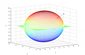
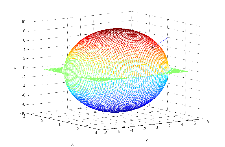
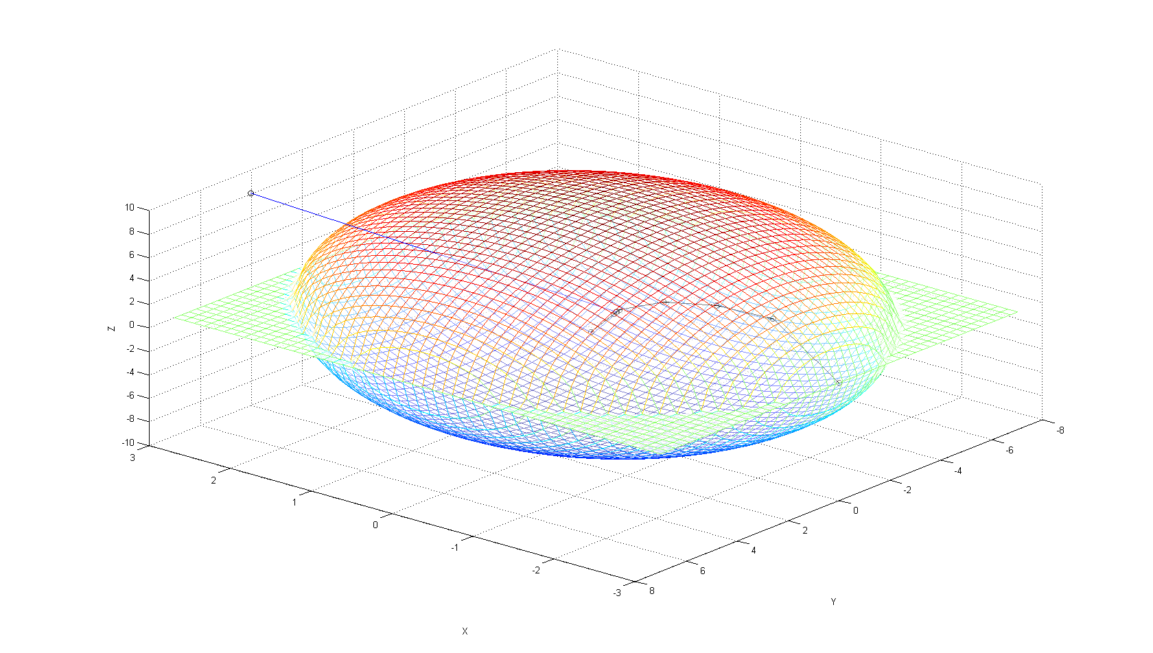
You can see the work done by the gradient search in the first figure, which is
shown below:
Full Size
Full Size
I know this doesn't look like the closest point, but, as you can see, the
script actually searches the mesh for the lowest value point and comes up with
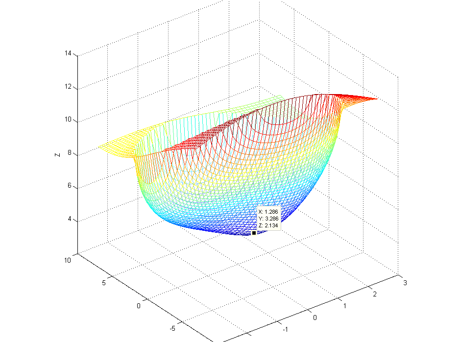
essentially the same point. To demonstrate, here is a 3d plot of the distance
of each point on the upper half of the ellipse to the target point, with the
minimum point labeled. This is the output of the script to figure 3. The
reason it doesn't look right is because of how matlab squashes everything to
fit the window.
[
Full Size
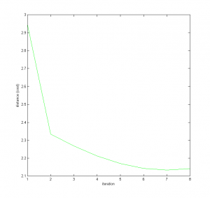
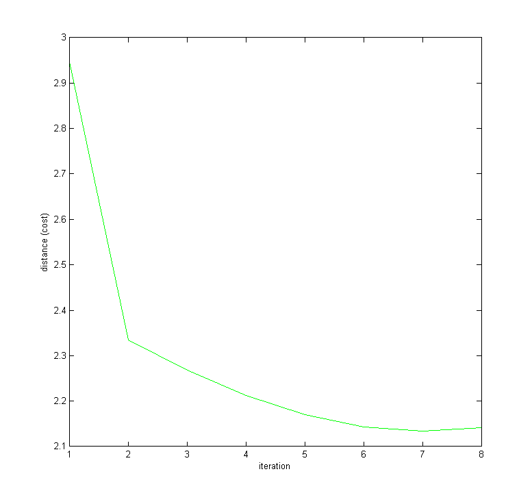
And finally here is a plot of the distance calculated at each iteration of the
loop. As you can see, it doesn't take many to find a value that is pretty damn
good.
Full Size
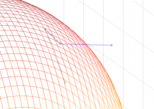
Steepest decent works pretty well right? Well, not always. The initial guess
used in the code above will save your ass, but steepest descent can suffer
from problems of local minima. Look what happens when I try an initial guess
on the other side of the ellipsoid.

Full Size
The algorithm get's caught in a local minimum, and converges to a very
precise, very incorrect solution.
LeGrange Method
This method is a little more elegant, but still ends up with a search
algorithm. However, in this case we're only doing a one dimensional search for
root-finding of a polynomial, which is a quite well documented problem.
In this method, we note that, since the constraint must be satisfied
everywhere, if we know the minimal cost $latex J^$ is achieved at a point
$latex \vec{q}^$, then we know that
$$ J^ = \sqrt{ (p_x-q^_x)^2 + (p_y-q^_y)^2 + (p_z-q^_z)^2 } $$
and we also know that if the augmented cost function is defined as
$$ L = J(\vec{q}) + \lambda f(\vec{q}) $$
which expands to
$$ L = \sqrt{ (p_x-q_x)^2 + (p_y-q_y)^2 + (p_z-q_z)^2 } + \lambda \left[
\frac{q_x^2}{a^2} + \frac{q_y^2}{b^2} + \frac{q_z^2}{c^2} - 1 \right] $$
then $latex L^ = J^$ and is also at $latex \vec{q}^*$ since the latter term
must be zero if the constraint is to be satisfied. We can then minimize the
cost function as we usually do, by taking the derivative with respect to the
independent variables, setting them to zero, and solving the system for the
unknowns.
First though, we note that the minimum of a square root expression will occur
at the same point as the minimum of the argument, so we will throw away the
square root part and solve instead for the minimum of
$$ L = (p_x-q_x)^2 + (p_y-q_y)^2 + (p_z-q_z)^2 + \lambda \left[
\frac{q_x^2}{a} + \frac{q_y^2}{b} + \frac{q_z^2}{c} - 1 \right] $$
We take the partial derivative of the augmented cost with respect to
the four unknowns and see that
$$ \frac{\partial{L}}{\partial{q_x}} = -2(p_x - q_x) + \frac{2 \lambda
q_x}{a^2} $$
.
$$ \frac{\partial{L}}{\partial{q_y}} = -2(p_y - q_y) + \frac{2 \lambda
q_y}{b^2} $$
.
$$ \frac{\partial{L}}{\partial{q_z}} = -2(p_z - q_z) + \frac{2 \lambda
q_z}{c^2} $$
.
$$ \frac{\partial{L}}{\partial{\lambda}} = \frac{q_x^2}{a^2} +
\frac{q_y^2}{b^2} + \frac{q_z^2}{c^2} - 1 $$
Setting these all to zero we can solve for the following
$$ q_x = \frac{p_x}{\lambda + \frac{1}{a^2}} = \frac{a^2 p_x}{\lambda +
1} = 0 $$
.
$$ q_y = \frac{p_y}{\lambda + \frac{1}{b^2}} = \frac{b^2 p_y}{\lambda +
1} = 0 $$
.
$$ q_z = \frac{p_z}{\lambda + \frac{1}{c^2}} = \frac{c^2 p_z}{\lambda +
1} = 0 $$
Substituting back into the fourth of the differentials we get that
$$ \frac{\partial{L}}{\partial{\lambda}} = \frac{a^2 p_x^2}{
\left(\lambda + a^2 \right)^2} + \frac{b^2 p_y^2}{ \left(\lambda + b^2
\right)^2} + \frac{c^2 p_z^2}{ \left(\lambda + c^2 \right)^2} - 1 = 0 $$
which simplifies to
$$ \frac{\partial{L}}{\partial{\lambda}} =
\begin{matrix}
& a^2 p_x^2\left( \lambda + b^2 \right)^2 \left( \lambda + c^2 \right)^2 \
& + \ b^2 p_y^2 \left( \lambda + a^2 \right)^2 \left( \lambda + c^2 \right)^2 \
& + \ c^2 p_z^2 \left( \lambda + a^2 \right)^2 \left( \lambda + b^2 \right)^2 \
& - \left( \lambda + a^2 \right)^2 \left( \lambda + b^2 \right)^2 \left( \lambda + c^2 \right)^2
= 0
\end{matrix} $$
Note that this is a sixth order polynomial in $latex \lambda$. Use your
favorite zero-finding algorithm (same as a root finding algorithm) to solve
for the zeros of this polynomial, (of which there should only be two as there
can only be one closest point, and one furthest point on an ellipsoid unless
the target point is along one of the axes), and you will find the minimum and
the maximum of your cost function. Once the solutions of $latex \lambda$ are
known, plug them into the equations above to solve for $latex q_x$, $latex
q_y$, and $latex q_z$. Then plug those into the cost function, and pick the
smaller of the two.
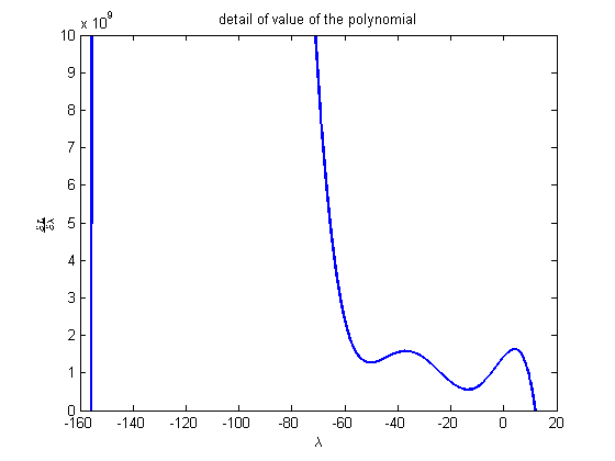
For the example problem used in the steepest descent code above, the
polynomial looks like this:
[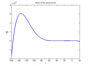
Full Size
Here is a detail view:
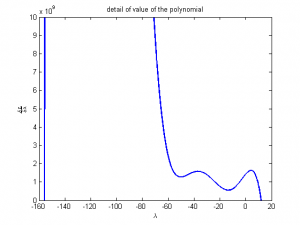
Full Size
As you can see, there are two solutions. Below is a matlab code that generates
the above graphs, and solves for the minimum point using a binary search. Note
that the search assumes that one of the values of \lambda that makes the
polynomial zero is to the left of the origin, and the other is to the right.
That is true for this example buy may not be in general (I didn't take the
time to work out why that may be the case ) so you may have to modify the
search to look for both roots on both sides of the origin.
    clc;
    clear;

    % define the ellipsoid parameters
    a   = 3;
    b   = 7;
    c   = 9;

    % createa a 100 x 100 point mesh for displaying the ellipsoid
    x   = linspace( -a, a, 50 );
    y   = linspace( -b, b, 50 );

    % calculate the z coordinates
    [X,Y]   = meshgrid(x,y);
    Zp      = c*sqrt(1 - X.*X/(a*a) - Y.*Y/(b*b) );
    Zm      = -Zp;

    % create the point we're going to calculate the closest too
    px = 3;
    py = 4;
    pz = 8;

    \lambda = -160:0.01:20;
    a2 = a*a;
    b2 = b*b;
    c2 = c*c;

    px2 = px*px;
    py2 = py*py;
    pz2 = pz*pz;

    lpa = \lambda + a*a;
    lpb = \lambda + b*b;
    lpc = \lambda + c*c;

    P = a2*px2*lpb.*lpb.*lpc.*lpc + …
        b2*py2*lpa.*lpa.*lpc.*lpc + …
        c2*pz2*lpa.*lpa.*lpb.*lpb - …
        lpa.*lpa.*lpb.*lpb.*lpc.*lpc;

    x = a2*px./lpa;
    y = b2*py./lpb;
    z = c2*pz./lpc;

    J = sqrt( (px-x).*(px-x) +  (py-y).*(py-y) +  (pz-z).*(pz-z) );

    close(figure(1));
    figure(1);
    plot( \lambda, P, 'b-', 'linewidth', 2 );
    xlabel('$\lambda$', 'Interpreter', 'LaTex');
    ylabel('$\frac{\partial L}{ \partial \lambda }$', 'Interpreter', 'LaTex');
    title('value of the polynomial');

    close(figure(2));
    figure(2);
    plot( \lambda, P, 'b-', 'linewidth', 2 );
    axis([-160,20,0, 1e10]);
    xlabel('$\lambda$', 'Interpreter', 'LaTex');
    ylabel('$\frac{\partial L}{ \partial \lambda }$', 'Interpreter', 'LaTex');
    title('detail of value of the polynomial');


    % start search by looking at the value of the polynomial at zero
    \lambda = 0;

    lpa = \lambda + a*a;
    lpb = \lambda + b*b;
    lpc = \lambda + c*c;

    P = a2*px2*lpb.*lpb.*lpc.*lpc + …
        b2*py2*lpa.*lpa.*lpc.*lpc + …
        c2*pz2*lpa.*lpa.*lpb.*lpb - …
        lpa.*lpa.*lpb.*lpb.*lpc.*lpc;

    % we need to store the start sign so that we know what sign we're looking
    % for in order to determine a zero crossing
    startSign = sign(P);

    % start our search in one direction
    i = 1;

    d\lambda = 1;
    lhs\lambda = 0;
    % start the forward search, we're looking for the first value we can
    % find that has a sign opposite that at the zero point
    while d\lambda < realmax/10
        rhs\lambda   = d\lambda;
        lpa         = rhs\lambda + a*a;
        lpb         = rhs\lambda + b*b;
        lpc         = rhs\lambda + c*c;

        P       =   a2*px2*lpb.*lpb.*lpc.*lpc + ...
                    b2*py2*lpa.*lpa.*lpc.*lpc + ...
                    c2*pz2*lpa.*lpa.*lpb.*lpb - ...
                    lpa.*lpa.*lpb.*lpb.*lpc.*lpc;

        % if we've discovered a sign change we can stop searching
        if( sign(P) ~= startSign )
            lhs\lambda = d\lambda/10;
            break;

        % if not, we need to grow the increment
        else
            d\lambda = d\lambda * 10;
        end
    end


    % now we can start a bisection search using the lhs and rhs that we've
    % just determined, which are exactly one order of magnitude apart
    error = (rhs\lambda - lhs\lambda)/lhs\lambda;
    while( abs(error) > 1e-2)
        \lambda = (lhs\lambda + rhs\lambda)/2;
        lpa         = \lambda + a*a;
        lpb         = \lambda + b*b;
        lpc         = \lambda + c*c;

        P       =   a2*px2*lpb.*lpb.*lpc.*lpc + …
                    b2*py2*lpa.*lpa.*lpc.*lpc + …
                    c2*pz2*lpa.*lpa.*lpb.*lpb - …
                    lpa.*lpa.*lpb.*lpb.*lpc.*lpc;

        if( sign(P) ~= startSign )
            rhs\lambda = \lambda;
        else
            lhs\lambda = \lambda;
        end

        error = (lhs\lambda - rhs\lambda)/lhs\lambda;
    end

    % store the found value
    \lambda1 = (lhs\lambda + rhs\lambda)/2;

    % now we search in the other direction;
    d\lambda = 1;
    rhs\lambda = 0;
    % start the forward search, we're looking for the first value we can
    % find that has a sign opposite that at the zero point
    while d\lambda < realmax/10
        lhs\lambda   = -d\lambda;
        lpa         = lhs\lambda + a*a;
        lpb         = lhs\lambda + b*b;
        lpc         = lhs\lambda + c*c;

        P       =   a2*px2*lpb.*lpb.*lpc.*lpc + ...
                    b2*py2*lpa.*lpa.*lpc.*lpc + ...
                    c2*pz2*lpa.*lpa.*lpb.*lpb - ...
                    lpa.*lpa.*lpb.*lpb.*lpc.*lpc;

        % if we've discovered a sign change we can stop searching
        if( sign(P) ~= startSign )
            rhs\lambda = -d\lambda/10;
            break;

        % if not, we need to grow the increment
        else
            d\lambda = d\lambda * 10;
        end
    end

    % now we can start a bisection search using the lhs and rhs that we've
    % just determined, which are exactly one order of magnitude apart
    error = (rhs\lambda - lhs\lambda)/lhs\lambda;
    while( abs(error) > 1e-2)
        \lambda = (lhs\lambda + rhs\lambda)/2;
        lpa         = \lambda + a*a;
        lpb         = \lambda + b*b;
        lpc         = \lambda + c*c;

        P       =   a2*px2*lpb.*lpb.*lpc.*lpc + …
                    b2*py2*lpa.*lpa.*lpc.*lpc + …
                    c2*pz2*lpa.*lpa.*lpb.*lpb - …
                    lpa.*lpa.*lpb.*lpb.*lpc.*lpc;

        if( sign(P) ~= startSign )
            lhs\lambda = \lambda;
        else
            rhs\lambda = \lambda;
        end

        error = (lhs\lambda - rhs\lambda)/lhs\lambda;
    end

    % store the found value
    \lambda2 = (lhs\lambda + rhs\lambda)/2;

    x1 = a2*px/(\lambda1+a2);
    y1 = b2*py/(\lambda1+b2);
    z1 = c2*pz/(\lambda1+c2);

    x2 = a2*px/(\lambda2+a2);
    y2 = b2*py/(\lambda2+b2);
    z2 = c2*pz/(\lambda2+c2);

    J1 = sqrt( (px-x1)*(px-x1) + (py-y1)*(py-y1) + (py-y1)*(py-y1) );
    J2 = sqrt( (px-x2)*(px-x2) + (py-y2)*(py-y2) + (py-y2)*(py-y2) );

    % print a little report
    message = sprintf( ['found zero crossings at \lambda = %f and %f', ...
                        'which corresponds to the points [%f, %f, %f]', …
                        'and [%f, %f, %f] with costs of %f and %f'], …
                       \lambda1, \lambda2, x1, y1, z1, x2, y2, z2, J1, J2 );
    disp(message);

    if( J1 < J2 )
        message = sprintf( 'the point of minimum distance is [%f, %f, %f]', ...
                            x1, y1, z1 );
    else
        message = sprintf( 'the point of minimum distance is [%f, %f, %f]', ...
                            x2, y2, z2 );
    end

    disp(message);
The output of this script is
found zero crossings at \lambda = 11.801758 and -155.810547which corresponds
to the points [1.297967, 3.223591, 6.982626]and [-0.183910, -1.835025,
-8.661880] with costs of 2.025472 and 8.844903
the point of minimum distance is [1.297967, 3.223591, 6.982626]
Which matches with the previous method. Sweet.
As a brief note, if the target point is inside the ellipse and along one of
it's axes, there may be an infinite number of solutions (all points on a ring
around the ellipse located at the coordinate of the target point will be the
same distance away). If this is a possibility in your application, make sure
you watch out for it and decide what the "right" solution is.
I hope this helps. Sorry I didn't write the code in c++ but it took long
enough to generate the results without doing that. Hopefully you can figure
out from the matlab code exactly what you need to. Matlab script isn't too
different from C++.
-Cheshirekow
